The journey to obtain a correct 3D model from all points of view of the IAR 80 airplane was – without any doubt – a joint effort of several generations of enthusiasts of the IAR 80 airplane and of the Romanian aviation in general.
Members of Sky Legend started working on an accurate 3D mock-up model using SolidWorks in December 2014, the first encouraging results being obtained in October 2015.
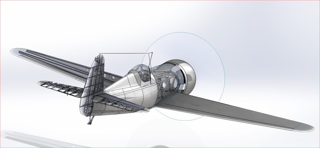
3D mockup (partial) – November 2017
We further present, exemplifying through pictures, the steps taken to correctly identify and realize the geometry, structure, controls, but also some of the installations of the IAR 80 aircraft.
Below, we find some “views” of the starting model for which tens, maybe a few hundred hours of study were invested.
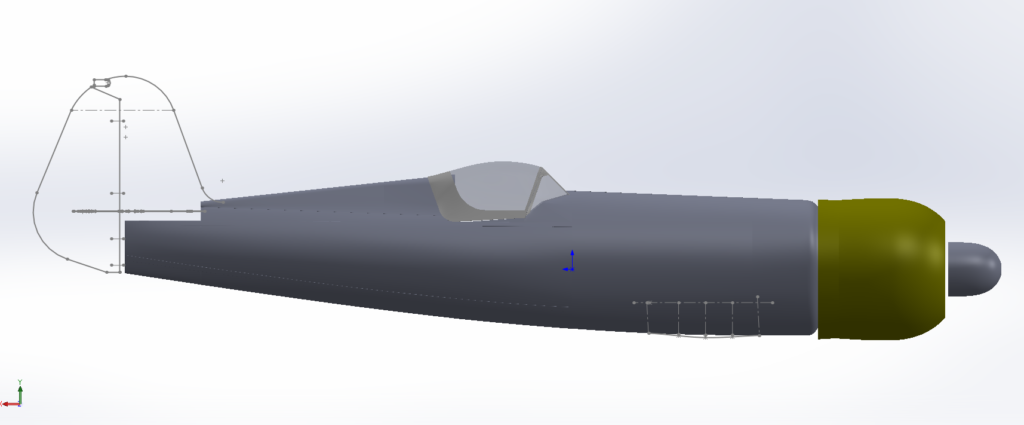
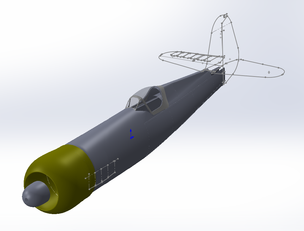
The fairings of the front of the fuselage are specific to an inverted inline V12 engine, atypical for a twin-star engine, this being a feature of the IAR.
Initial fuselage version – October 2015
The rear of the fuselage, of a semi-monocoque construction, was rebuilt using the execution drawings of the frames and those of the respective assemblies, but also by studying the available pictures and more.
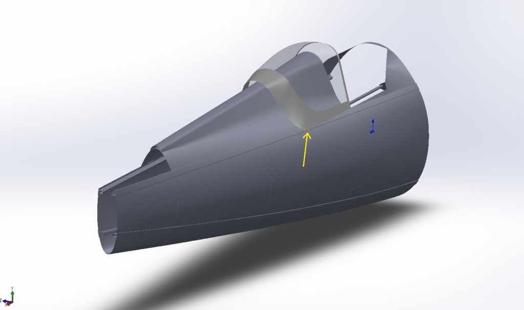
Frames of the semi-monocoque rear fuselage
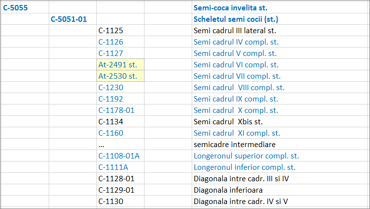
The rear fuselage, built similarly to that of the PZL 11F aircraft, consists of 10 main frames and 5 intermediate frames, as well as 4 longerons with the omega-shaped section. Most of the shell elements have been designed by the factory engineers, such as frames III, IV, V, VIII, IX, X, Xbis, X. Frames VI, VII are identical to those of the PZL, according to the part numbers in the cartridges of the factory drawings.
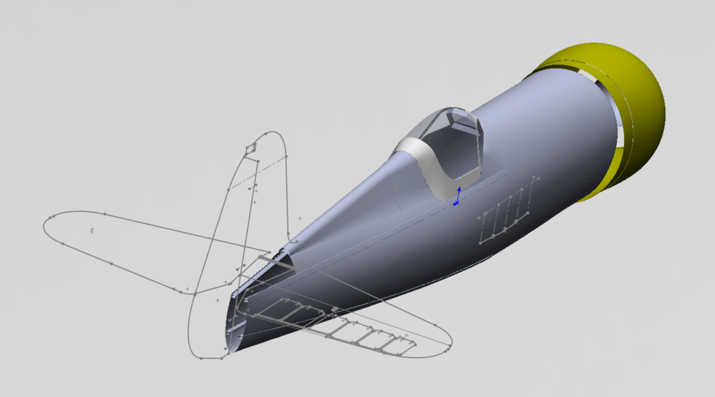
Completed shell – October 2015
Rear fuselage and mount details – February 2016
In addition, we present below the first 3D shapes made using drawings from the Romanian “Modelism” magazine, but which were later abandoned due to accuracy reasons.
The IAR80R project aims to rebuild the Romanian IAR 80 aircraft, developed during the onset of World War II, being operational on the front between 1941-1945 and then as a training aircraft until 1952. After the war, the number of IAR80 aircraft decreased considerably, and there are currently no recovered, original copies. The main objective of the project is of historical restitution, offering to the general public in Romania, but also abroad, the opportunity to experience a historically accurate replica of the original IAR80 aircraft, in 3D virtual mock-up, in static and flight demonstrations. In this sense, important historical documents from the construction period of the aircraft (1939-1943) were recovered and these will largely constitute the foundation of the project.
The ‘Sky Legend’ Association updated the information and objectives within the IAR80R project, structured and planned from a budgetary and schedule point of view all the activities to be carried out in the project. Thus, a new Edition of the Statement of Work (SoW) was made and discussed within the Team.
The association, established in January 2019, initiated this project on a voluntary basis with history and technology enthusiasts, especially with the desire to recover the Romanian aviation technical history through specific activities, services or actions. The project was started from private initiatives and later integrated into the actions and purpose of the “SKY LEGEND” Association.
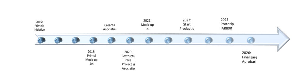
The evolution of the preliminary stages as well as the current situation of the project are illustrate din the following ‘Road map’:
2015 – The first private initiatives
2017 – The first technical measurements
2018 – The first Mock-up 1: 4 Solidworks scale
2018 – Creation of the SKY Legend Association
2019 – The first articles, interviews, production tests (technical activity, history, media)
2020 – Restructuring the Association and declaring the Purpose of the Project to the Romanian Aeronautical Authority
2020+ – Project Development (after the revised Specifications v 1.0 / 2020)
Roadmap IAR80R project
2015: first initiatives; 2018 first mock-up 1:4; establishment of the association; 2020: project restructuring; 2021: 1:1 mock-up; 2023: production start; 2025: IAR80R prototype; 2026: final approvals
Scope and objectives of the project
According to the Statute, the ASSOCIATION aims to achieve the following objectives that fall within the scope of the IAR 80R aircraft project: retrieving the original information, creating a 3D model and creating a 1: 1 scale replica, functional, in airworthy condition.
Main purpose and objectives:
Building up a documentation fund containing data and information related to the IAR 80 aircraft: blueprints, manuals, books, drawings, photographs, films, etc.
Creating an accurate 3D Mock-up based on the original documentation
Realization of the production documentation of the replica airplane and the associated manufacturing setup designed by the association members in collaboration with third parties
Realization in collaboration with specialized companies of the IAR 80R aircraft
Carrying out airworthiness ground and flight tests
Aircraft registration, operation and participation in in-flight demonstrations
Project Structure
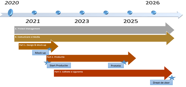
To allow for the diligent follow-up of such a unique, complex and long-lasting undertaking, the project has been broken down into several relevant work packages, with tasks that are easily identifiable, time bound and with well defined objectives. Alongside chapters such as Project Management and Communication and Media, which will take place throughout the project, the Technical chapter has been divided according to the specifics and complexity of the activities to be carried out.
The technical project will be structured in 3 main parts: ‘Design and Mock-up’, ‘Aircraft production’ and the continuous follow-up of ‘Quality and Safety’. Each of them contains an internal structure of specific work packages. With the exception of the recovery of the original technical documentation, the choice of the type variant for the 3D design and subsequent 1:1 prototype production, as well as the choice and acquisition of the engine and equipment, the activities associated with the 3 main technical will have a staggered start.
The project structure with its main chapters is presented graphically in the figure below:
A. Project Management; B. Media and comms; Part 1. Design & mockup; Part 2. production; Part; Quality & safety’ B1> historical information; B2. Project promotion; B3. website; M2. documentation & archiving
The Technical Project and the structuring of the objectives of each Technical Part were established taking into account their grouping as follows:
Part 1: ‘3D Design and Mock-up’ covers:
Historical and technical documentation – Recovery of technical and historical documents, scanning, archiving, classifying, editing and transforming into usable format for 3D mpdelling
3D design – 3D models (made in Solidworks) according to the original and buildable variants
CFD and FEM verification and validation calculations,
Media and Communication – Historical articles, articles about the project activity and www presentation;
This part will cover mainly activities related to the design, 3D construction, analysis and verification as well as project technical documentation through voluntary participation of ‘Sky Legend’ members.
Part 2: ‘Production’ covers the preparation for production, the actual production and following maintenance steps:
Pre-production information, production capacity and suppliers – Parts nomenclature, Supplier list
Information and Engine acquisition – Engine acquisition (final phase)
Design and preparation for procurement and production – 3D / 2D; production and procurement of parts, manufacturing & test tools and equipment
Production – Delivery list, production
Assembly and Installation – Logistics, components assembly and final aircraft delivery
Design and purchase of equipment and machinery for maintenance and operation – Equipment, machinery for maintenance and operation
Production and archiving documentation – Archive and project documents
Media and Communication – Articles about the project manufacturing activities
Part 3: ‘Quality and safety’ covers quality and flight safety processes and their associated documentation as well as the mandatory airworthiness documentation. The maintenance phase, the technical project documentation (manuals) and the first airborne demonstrations at aviation events will be covered by this chapter.
Transport and maintenance – Transport and maintenance rules; Maintenance manual
Airworthiness documentation – Ground and Flight Tests, Applications and Official Flight Authorization Documentation (Flight Certificate)
Participation and preparation for Exhibitions and Meetings – Flight logs, Procedures, Documentation
Project documentation and archiving – Archive and Project Documents
Media and Communication – Articles, posts and www presence;
Project planning
The time given to the development of the project is also related to a number of risk factors. Not only the technical difficulties such as finding a compatible engine, the similarity and adaptation of hydraulic and electrical systems and installations, the production of a functioning aircraft and the necessary airworthiness approvals, but also the social risks such as: public interest in particular during the Covid pandemic and the gradual loss of the generation of the ´40s that developed and have flown this aircraft.
Taking into account the novelty of the project and the difficulties that may arise in any stage and chapter of it, the IAR 80R Project is expected to run for a minimum of 5 years. A short ‘Roadmap’ presentation is illustrated in the following chart:
Project roadmap
Project budget and costs
Regarding the Costs and Budget allocated to the project, for a first estimate we start from the following assumptions:
Part P1. ‘Design and Mock-up’ and project organization will be sustained by the members of the Association in the form of active, voluntary involvement based on initiatives as well as experience, knowledge and skills.
Part P2. Production and operation will be partially budgeted. It is considered that the acquisition of parts, their production, assembly as well as the maintenance and operation of the aircraft (product) will have to be financed. For this purpose, sponsorship contracts will be pursued, attracting investments to cover the necessary expenses. The aim is to involve partners in the project in the form of sponsorship or collaboration. Where appropriate, the level of involvement, interests or various other considerations will be concluded in collaboration agreements, partnerships or sponsorship agreements.
Part P3. Quality and Safety will also be partially budgeted. The execution of ground and flight tests, as well as the expenses necessary for maintenance and operation but also the expenses with the necessary documentation for flight approvals and manuals will be included in the Project Costs. The aim is to obtain partnerships and sponsorships that can cover these expenses.
The estimated budget for the entire project includes the activity of Members and partners on a voluntary basis, which is estimated to no less than 14,000 hours. The costs of purchasing parts, installations, subassemblies or materials as well as the production and testing parts are initially estimated at a value of approx. 550,000 Euros. Collaborations, sponsorships and the active involvement of project partners are beneficial and encouraged in the project.
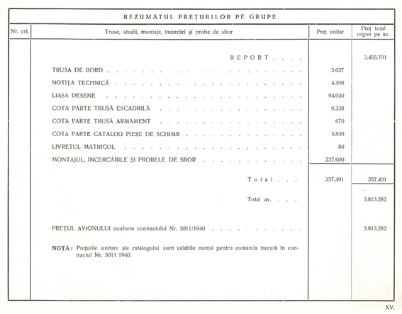
A novel historical finding, with the estimates of the project dating back to 1941, can be found in the IAR81 Spare Parts Catalogue (1941 edition):
The Sky Legend Association, through the activity of the project, will make a major contribution to the recovery of the original documentation, its transformation into digital information, its preservation over generations and last but not least, making it available to the general public. Generations of aeronautical engineering students, but also the interested public will be able to experience a virtual 3D model of the plane that can be used for educational purposes and for the training of new engineers and aviation enthusiasts. The realization of a historically accurate 1:1 airworthy IAR 80/81 replica is the essence of the project contributing to the restitution of the historical heritage.
Our wish is for IAR 80R to become a proof of Romanian technical ingenuity and a source of inspiration for future generations of engineers, aviators and enthusiasts of technology and aviation in Romania and anywhere else in the world.
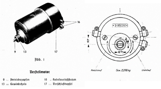
The electric pitch adjustment motor (VDM 9-9500.12) was produced by Bosch, being the same type of motor that equipped the Messerschmitt aircraft from the initial series.
The electric pitch adjustment motor (VDM 9-9500.12)
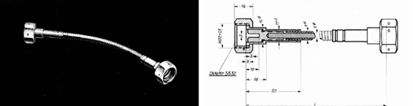
The VDM 9-9500.12 motor was a 24V, two-way, reversible direct current motor to allow adaptation to the direction of rotation of the propeller and with a rated power of 80W at 2500 rpm. The connection with the blade drive gear and the VDM pitch-limit controller 9-9500.52 was made through a flexible shaft compliant to DIN Kr 5532.
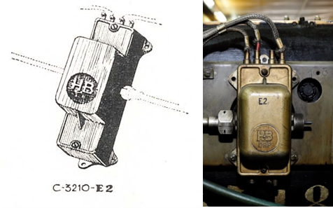
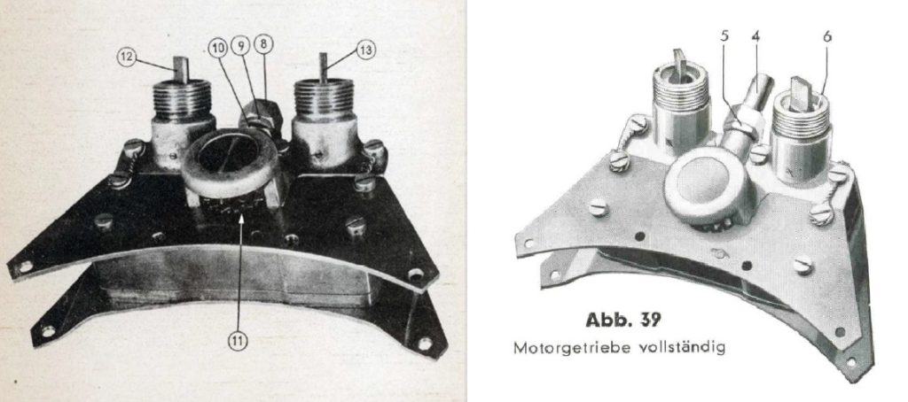
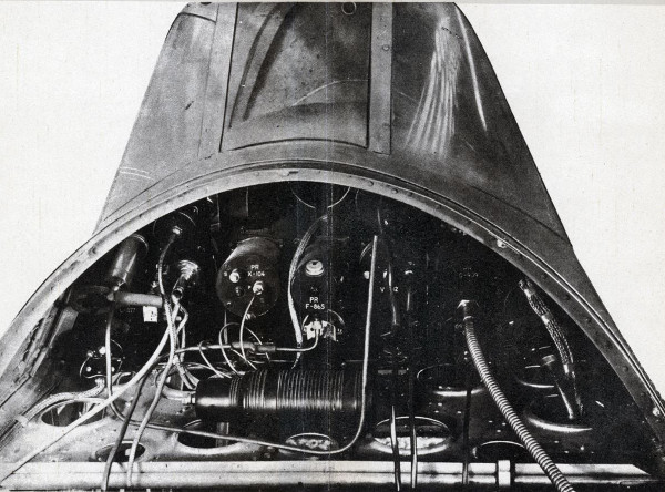
The propeller pitch-limit controller was of the H&B VDM 9-9500.52 type (C-3210-E2 in the I.A.R. nomenclature). The figure below shows a drawing from the I.A.R. catalogue and a photo of the same controller installed on the Messerschmitt.
propeller pitch-limit controller: IAR 80 / Bf-109
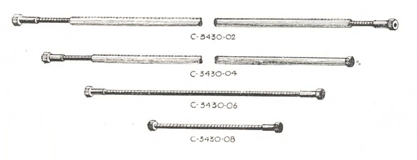
All electro-mechanical components in the propeller assembly were connected by flexible shafts manufactured at I.A.R. according to DIN Kr. 5532
I.A.R. manufactured flexible shafts
original VDM flexible shafts
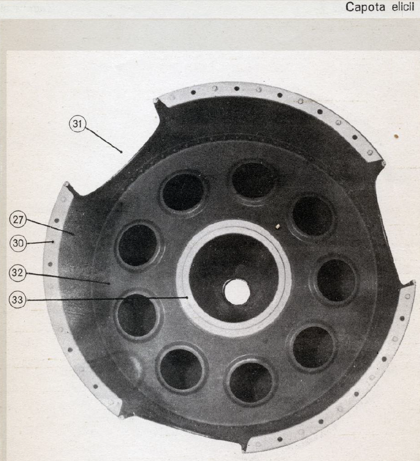
The rest of the components in the propeller assembly (main gear, motor gear and propeller hub) were identical to those that equipped the Bf 109E as can be seen from the images below.
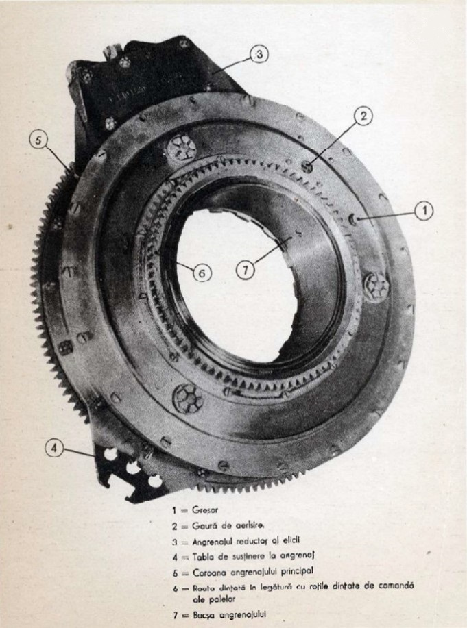
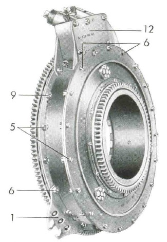
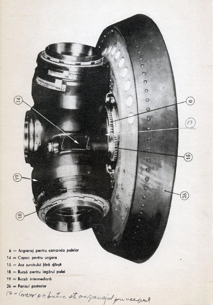
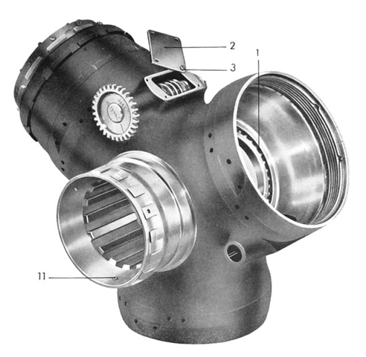
Propeller main gear (VDM 9-11014.56)
Angrenajul VDM 9-11014.56: IAR80 / Bf-109E
Motor gear (VDM 9-0142.62)
Angrenajul motor VDM 9-0142.62: IAR80 / Bf-109E
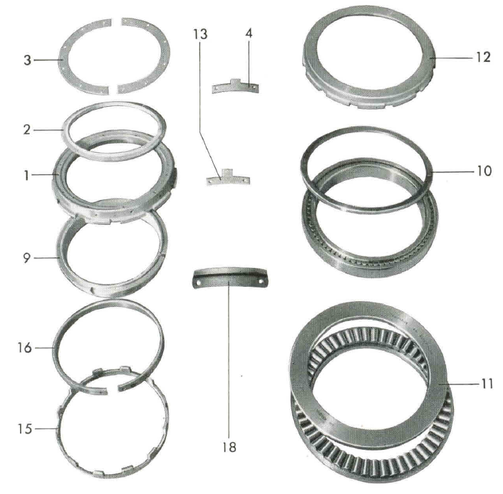
Propeller Hub (VDM 9-081.25)
The figure below shows the blade bearing type VDM 9-11 081.40 compatible with the hub VDM 9-081.25., most likely the same type used by the I.A.R. 80/81.
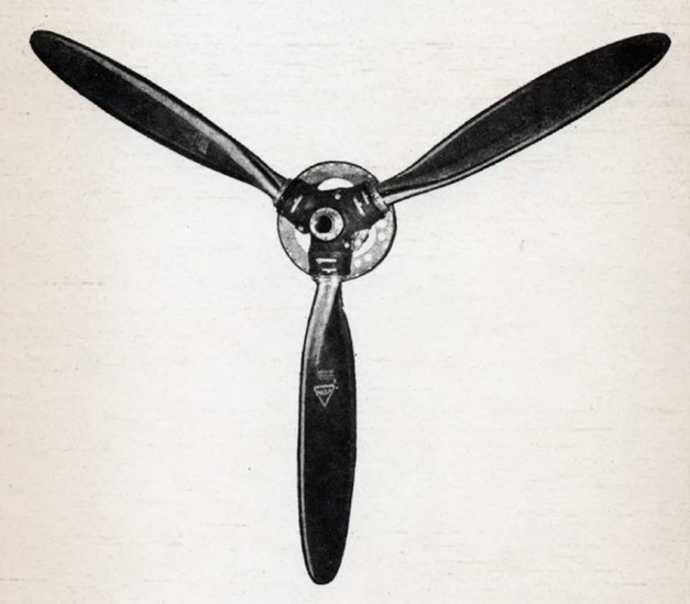
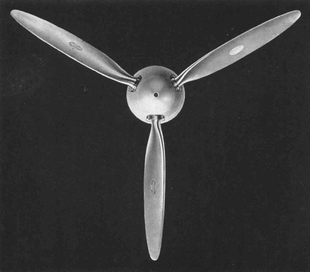
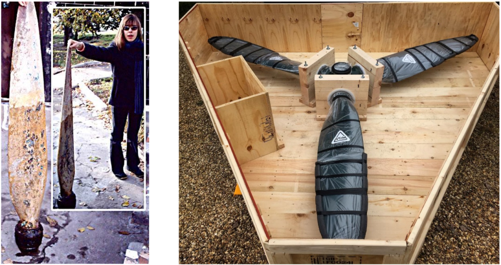
The VDM propeller blades
We do not have precise information on the VDM 9-11 131 propeller blades but we can assume with a high degree of certainty that they were a mirror copy of the blades mounted on Bf 109E given that both aircraft used common VDM components, the propeller dimensions were the same (3 m diameter) and the power of the DB601A and IAR engines 14K similar. The similarity can be seen in the illustrations below.
IAR 80 propeller (left-hand tractor)
Bf-109 propeller (right-hand tractor) -early VDM oval logo (1939)
Bf-109E propeller (VDM 9-11.081 A, year 1941) – VDM classical triangle logo
The first photo depicts one of the propeller blades of the IAR 80 C aircraft Nr. 264 piloted by NCO Olaru Aurel shot down on the 4th of February 1944 over the Black Sea as a result of an error by the German air defense and recovered by Ukrainian divers in the 90s. [14]
The second shows a modern replica of the VDM propeller for the Fw-190
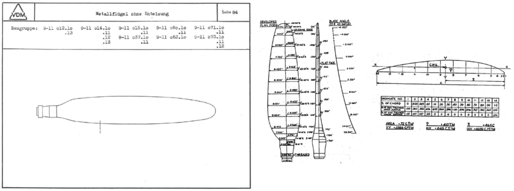
VDM propeller geometry
The propeller blades mounted on Bf 109 E with manual VDM system (VDM 9-11 081 A) were of the type 9-11 073.10 illustrated in cross section in the figure below (excerpt from the catalog of VDM parts Ed. 1944 [8]). The diameter of the propeller was 3 m and the diameter of the blade fitting was 107 mm.
The same type of propeller was equipping the Jumo 211 A engines of the Heinkel He-111 H1, H-2 bombers. The image on the right shows the developed planform of the blade surface, the angle distribution and the blade profile of the Heinkel 111 propeller [4]. Note: due to the projection, the blade looks wider compared to the cross section.
The propeller blades were made of Duralumin with the following composition: 3.30% Copper, 0.46% Iron, 0.43% Silicon, 0.68% Manganese, 0.70% Magnesium, 0.02% Titanium and the rest Aluminum.
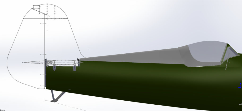
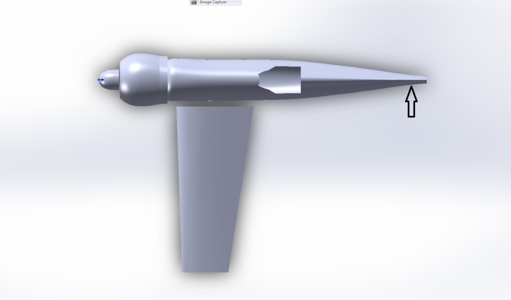
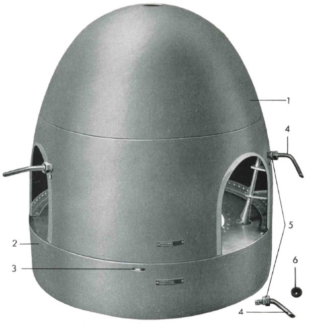
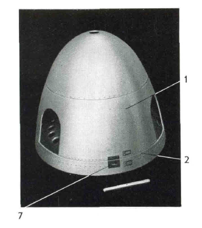
The propeller spinner
The propeller spinner of the I.A.R. 80/81 had two shapes, a more common rounded one and a variant with a more elongated tip. These variations do not seem to be related to a particular type but rather driven by logistical considerations. Assuming that they complied with the VDM models for propeller main gear compatibility, the most likely types appear to be those used on the Bf-109E for the elongated tip variant (VDM 11 081.30) and the VDM -11 257.32 type for the rounded tip variant.
VDM – 11 257.32 (Fw 200)
VDM 11 081.30 (Bf109E, 1939)
IAR80 spinner seen from below
VDM 11 257.32 spinner (Fw 200, BMW 323R)
IAR 80 propeller spinner
P.S: special thanks to Franciszek Strzelczyk, who’s valuable feedback allowed us to improve the quality of this article
Author: Răzvan Mărgăuan
Bibliography:
1. Notița tehnică a avionului de vânătoare I.A.R. 80 cu motor I.A.R. 14 K. IV. C. 32, Brașov 1941
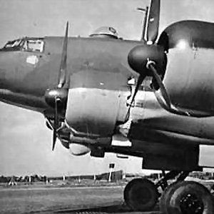
In mass production the I.A.R. 80/81 aircraft were equipped with VDM (Vereinigte Deutsche Metallwerke) propellers, a German manufacturer with factories in Frankfurt-am-Main-Heddernheim and Hamburg, Gross-Borstel which equipped virtually the entire Luftwaffe during the war.
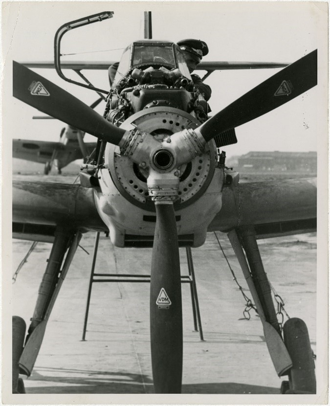
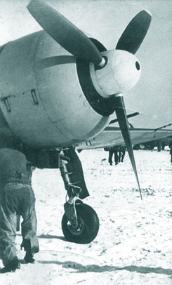
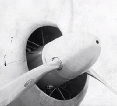
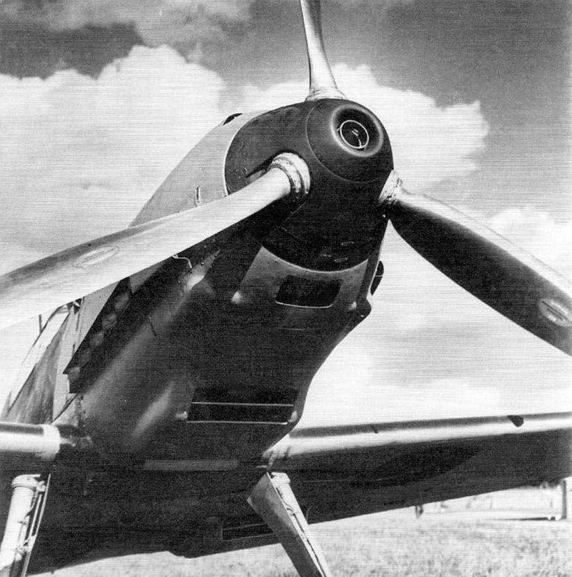
On the I.A.R. 80 prototype we can observe the typical VDM hollow spinner of an unusual long shape, sporadically found in the mass production series, as well as an early VDM oval logo.
Propeller of the IAR 80 prototype with a VDM oval logo
Propeller of the Bf-109 E with a VDM oval logo
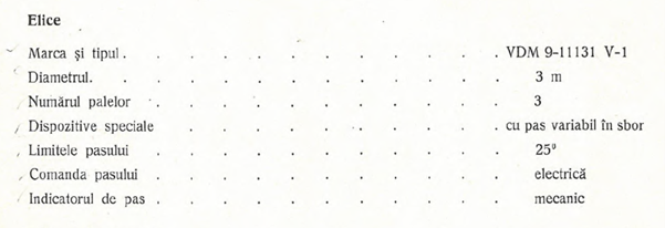
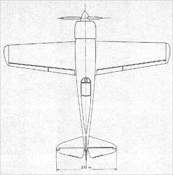
I.A.R. 80/81 series were equipped with three-blade metal propeller with variable pitch type VDM 9-11 131. The propeller pitch was adjusted manually by the pilot through an electrically operated system, this system being used throughout production. The following table lists the main characteristics of the propeller extracted from the airplane technical note: [2]
Propeller, Brand and type: VDM 9-11131 V-1; Diameter: 3 m; Nbr. of blades: 3; Special equipment: variable pitch; Pitch limits: 25 degrees; Pitch control: electrical; Pitch indicator: mechanical
The VDM type 9-11 131 was not a common type and is not found in the VDM parts list of the time [8], instead, as we will see below, the components are practically identical to those used in the initial variants of the Messerschmitt Bf 109 E. The main difference is that the IAR engine 14 K IV c 32 had a counterclockwise rotation (looking from the cockpit), opposite to the DB 601 A, N engine with which equipped the Bf 109 E.
To better understand the operation of the VDM system which equipped the I.A.R. 80/81 it is helpful to review the operating principle of the variable pitch propeller.
The propeller of an aircraft is essentially an airfoil which, like the wing of an aircraft, will provide the best aerodynamic efficiency at a certain angle of attack, the latter being generally determined by the blade angle relative to the central axis of the propeller and the air speed. In the case of a fixed pitch propeller, the optimum efficiency can only be obtained at a certain flight regime, for example during climb or constant speed cruise. To eliminate this shortcoming, the variable pitch propeller allows to adjust the blade angle and implicitly the propeller pitch (the distance traveled by the tip of the propeller along the central axis at a complete rotation). Thus, different values of the engine manifold pressure correspond to different speeds and positions of the propeller blades.
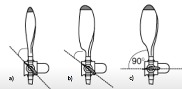
The diagram below shows 3 typical positions for:
a) Low pitch, maximum engine RPM and low speed (take-off, climb)
b) High pitch, nominal engine RPM and high speed (cruise flight)
c) Feathered, for minimum drag in case of engine failure
Depending on the propeller pitch adjustment mode, VDM systems were of two types:
Manual system in which the propeller pitch is selected by the pilot on the ground or in flight. This system could be converted to the automatic model.
Automatic system, equivalent to contemporary ones, which was equipped with a constant speed unit (governor) that maintained a constant propeller speed by automatically adjusting the pitch at different airspeeds or engine power settings.
A unique feature of the VDM systems was the pitch indicator which we will address further on in this article. In both variants, the pitch indicators could be of the mechanical or electrical type.
The system used on the I.A.R. 80/81 was the manual one with mechanical indicator, this type of indicator being characteristic of single-engine airplanes. Unfortunately, the system was not improved by adapting to an automatic one, although this could be done relatively easily (as was the case with the Bf 109-E). As a matter of fact Maj. Hendrick of the Luftwaffe who tested the IAR 80 No. 2 on March 23rd 1941 highlighted the absence of the automatic system as a major shortcoming. It is not clear to the author which considerations constrained the I.A.R. manufacturer, perhaps the hope of equipping a more powerful engine, perhaps driven by cost or logistical considerations. Regardless, this limitation remained an important disadvantage for the I.A.R. 80/81, especially in air combat.
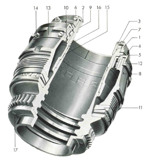
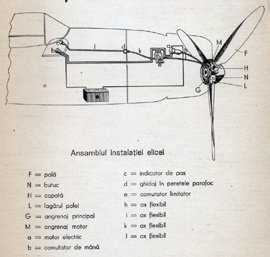
The propeller installation of the I.A.R. 80/81 is described in the diagram below [1]
Propeller installation
F = blade; N = hub; H = spinner; L = blade root; G = main gear; M = motor gear; a = electrical motor; b = control switch; c = pitch indicator; d = firewall guide; e = pitch limit controller; h, i, k, l = flexible shaft
The electrical motor (a) was connected to the blade angle adjustment main gear (G) by a flexible shaft (h). A similar flexible shaft (i) connects the main gear to the pitch limit controller (e). The latter had the role of keeping the blade angle within a predefined range of values, in the case of I.A.R. 80/81 this range being 25°. On the opposite side the limiter was connected to the mechanical indicator by two other flexible shafts (k, l) passing through the firewall. The manual switch (b) controls the increase or decrease of the propeller pitch by means of the limiter which in turn drives the electric motor.
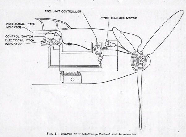
The following figure shows an English translation of the diagram from the VDM maintenance manual, Ed. 1939 [6]. Unlike the diagram in the I.A.R. manual, it also illustrates the variant with electrical pitch indicator with an additional capacitor on the circuit of the electrical indicator to limit interferences, the rest of the components being identical.
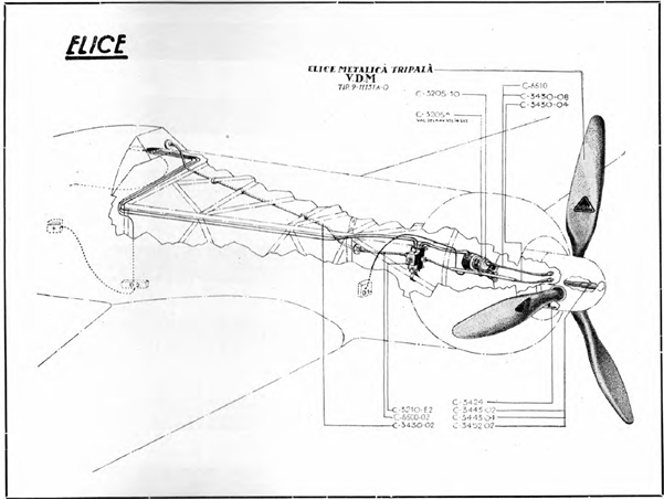
Most propeller components were supplied by the German manufacturer V.D.M. but some of the accessories (flexible shafts, mounting brackets, etc.) were produced at the I.A.R. factory, for example the flexible shaft of the electric motor C-3430-04 according to the I.A.R. nomenclature and other components illustrated in the diagram below:
3 blade VDM propeller type 9-11131 A-O
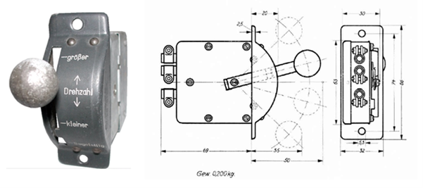
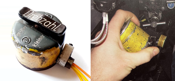
The pitch control switch (type VDM 9-9501) was a lever switch specially developed to operate the VDM adjustable propeller and was used to control the VDM 9-9500.12 electrical motor.
The VDM pitch control switch (early versions)
By continuously pressing the switch, the blade angle is adjusted, and implicitly, as shown above, the engine speed (‘Drehzahl’) at a certain position of the throttle lever. The switch had three operating positions and one stop position. In the ‘-großer’ position, the electric motor was operated in the direction of reducing the blade angle thus increasing the speed until the minimum blade angle was reached when the limiter automatically disengaged the motor. In the “-kleiner” position the engine was operated in the opposite direction resulting in a decrease in speed up to the position of the maximum angle. When the switch lever was released, it automatically returned to the neutral position at which the control motor was stopped. In the ‘Segelstellung’ position, the switch lever was held in place by a slot in the front panel. In this position, required for gliding in case of engine failure, the propeller pitch automatically returned to the large pitch corresponding to the maximum blade angle and the engine stopped automatically.
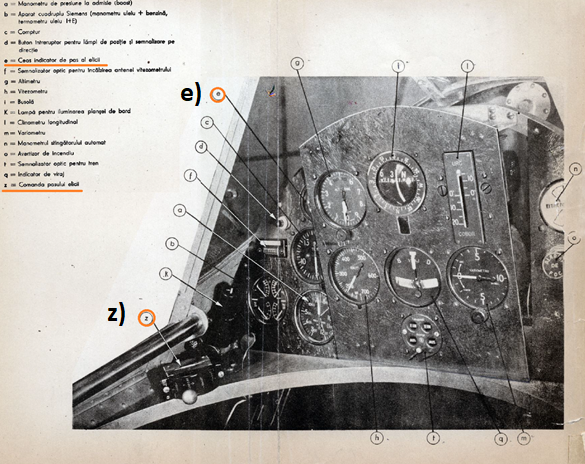
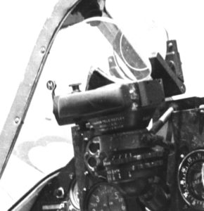
The switch was installed to the left of the pilot, above the throttle lever (position (z) in the figure below).
Fig. 1. IAR 80 Instrument panel
This type of switch was also used in the initial versions of the Bf 109 E and was later replaced with a more ergonomic system attached to the throttle, a forerunner of the modern HOTAS system (Hands On Throttle and Stick) used today on military aircraft. Unfortunately the I.A.R. did not benefit from similar improvements.
Manual pitch control on the Bf-109 (late E versions onwards)
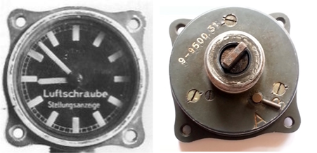
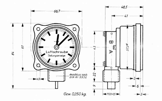
The propeller pitch indicator
The position of the propeller blades could be read on the mechanical indicator VDM 9-9500.30 / 31, this type of indicator being characteristic of Luftwaffe aircraft.
The VDM propeller pitch indicator
The indicator was in the shape of a clock without numerical markings and was read in the same way (for example, the engine was started at 10 o’clock, take-off at 12 o’clock, dive at 09:30, etc.). The minimum angle corresponded to 12 o’clock and 2200 engine RPM and the maximum to 09:30 o’clock and 1650 RPM.
This way pilots had an easy way to remember and set the relative positioning of the blades for different flight regimes, not being interested in the exact value of the blade angle. British engineers who analyzed the VDM system during the war could not understand the purpose of this indicator and considered it superfluous given that Allied aircraft were equipped with a lever to adjust the engine speed that worked the same as the throttle. By positioning this lever forward or backward, the pilot obtained the desired speed, the relative position of the lever having in this case also the role of approximate indicator of the propeller pitch.
On the I.A.R. the VDM pitch indicator was located at the top left of the instrument panel (see position (s) in Figure 1 above representing the instrument panel).
A switch installed behind the indicator (marked A / B) allowed for changing the direction of rotation.
Author: Răzvan Mărgăuan
To be continued …
Bibliography:
1. Notița tehnică a avionului de vânătoare I.A.R. 80 cu motor I.A.R. 14 K. IV. C. 32, Brașov 1941
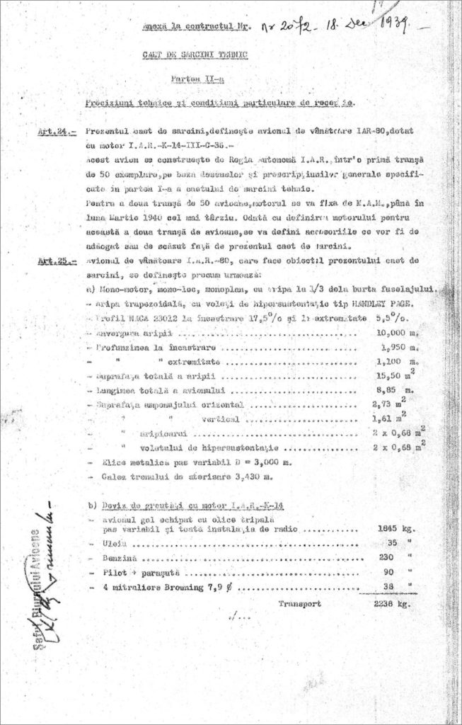
In order to start the mass production, the Ministry of Air and Navy (Ministerul Aerului și Marinei – M.A.M.) draws up a Statement of Work (SOW), annex to Contract No. 2072/18 Dec 1939. This SOW places an order for a first batch of 50 fighters of the IAR 80 type, which were going to be manufactured by Regia Autonomă I.A.R. of Brașov.
The SOW specifies that the first 50 aircraft will be equipped with the IAR-14K IIc32 engine with an option for a second batch of 50 aircraft. The M.A.M. was going to specify, by March 1940 at the latest, the final engine of choice. It was probably hoped that Junkers was going to keep its promise to deliver the Jumo engines as initially t1hought.
To be noted that in the SOW I.A.R. has preserved the characteristics of the prototype and not of the modified variant – no. 1.
First page of the Statement of Work
Production will begin in January 1940, the first deliveries to be expected towards the end of the same year.
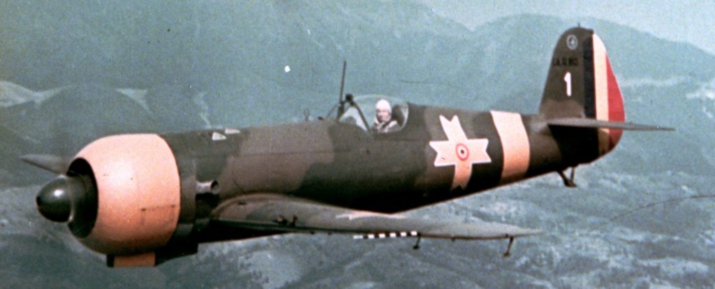
No. 1 aircraft flew for the first time on July 10, followed by No.2 on July 19. The first five aircraft were ready for delivery on November 29, 1940. By February 20, 1941, the first batch of 20 aircraft had been delivered, and by April 16, the entire batch of 50 IAR 80 aircraft had been delivered.
IAR 80 – No. 1
During mass production several changes were made depending on the requirements of the beneficiary or from observations made following flight tests.
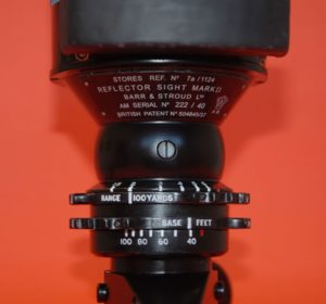
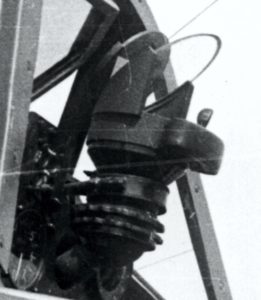
Starting with number 21, the existing gunsight is replaced with a Goerz type. The related story is quite interesting:
"The British Air Ministry has launched increasing orders for the Bar & Stroud reflex gunsight which was considered top secret as it was going to equip Spitfires and Hurricanes. The company could not meet the orders and the Air Ministry asked them to find an external supplier. This was going to be CP Goerz of Vienna. The British Ministry of Air approves the contract and a set of secret drawings together with a complete gunsight will be sent to Austria. Despite of the Anschluss (March 12, 1938) the Vienner company will honor the contract with The British Ministry of Air until the entry of Great Britain into the war delivering about 700 gunsights known as GM2 Mk II.
Its quality was considered superior to the British original [4.] "
from left to right: The Bar & Stroud gunsight, the Goerz gunsight, the IOR-Telereflex gunsight
And this is how the IAR 80 ended up to be equipped with an Austrian-made gunsight, manufactured under British license, identical to the ones used on Spitfires or Hurricanes, and supplied by Germany!.
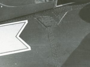
Regarding the fuselage, during testing it was found that deformations would occur at the level of the V frame. It was decided to reinforce it with a belt initially mounted on the outside, fixed with four rows of rivets.
From left to right: without the reinforcement belt; exterior belt; interior mounted belt seen from the outside
The reinforcing belt at frame V was kept on the outside until series number 95. From 96 onwards it was mounted on the inside and was riveted to 3 rows of rivets.
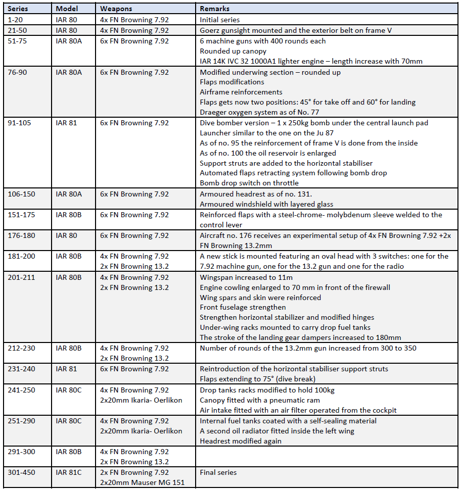
Production was split into several batches of aircraft, with different specifications as shown in the following table:
During production there were various problems reported by pilots flying the aircraft – components that malfunctioned abnormally often (instruments, sensors …) or serious structural defects – V-frame deformation, frequent rupture of the electron compass of the landing gear …
We will talk about all this in the next chapter.
to be continued: problems, problems …
Bibliography:
1. Dan Antoniu, George Cicos,IAR-80 "Le Héros Méconnu",Editura TMA Paris 2008
2. Horia Stoica, Dan Antoniu, Industria Aeronautică Romană I.A.R. 1925-1948, Braşov 2020
3. Radu Brînzan, Vânător Romanian Hunter - The I.A.R.80 & I.A.R.81 in ultimate detail, MMP 2014
Following the completion of the prototype and of the corresponding flight tests it became obvious that changes were needed leading to specifications for the mass production aircraft. According to the “Technical Specifications, Part II”, Annex to Contract No. 2072/18 Dec 1939, the Defense Ministry launches a first order for a number of 50 IAR 80 fighter planes.
There is a legend that in brief says that the first IAR 80 resulted from the modification of the prototype. This statement must be carefully considered. After a thorough study of several photos with the first IAR 80 aircraft, it seems that a new prototype has actually been built, and the differences between the prototype and the number 1 are very large, both in shape and size.
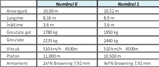
Characteristics of the prototype (No. 0) vs. No. 1
From the available photos, it can be seen that this first plane also underwent several modifications, which is why it must be carefully analyzed to understand how it “evolved” to the first series of planes.
For analysis, we will consider three photos of the plane credited as number 1.
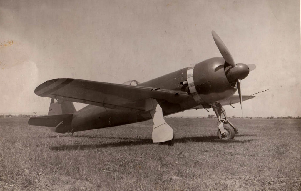
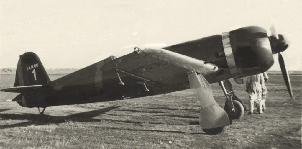
The first variant
IAR 80 – ‘ earliest version’
From this first photo, we can observe the following characteristics specific to the entire mass production series:
the cockpit is redesigned, being closed with a sliding plexiglass canopy;
the engine cowl is completely new, with a circular profile at the front and an oval at the rear;
in this variant we also notice the cooling flaps of the engine, adjustable in flight, which we will find in all subsequent series;
the front fuselage has been completely redesigned and lengthened by 74 mm, due to the modification of the engine mount;
an carburetor air intake was mounted under the hood;
the wing is enlarged on the aileron area with a rib, which has three hinges compared to two of the prototype, the aileron being equipped with two counterweights; position lights are added at end of the wings;
the horizontal tail was completely redesigned, having a strengthened structure and increased surface;
the horizontal stabilizer struts were removed;
the tail was also completely redesigned, with an enlarged surface; distinctive from the prototype, the upper rib of the rudder is oblique;
for practical reasons, the movable cover from the base of the landing gear is removed;
last but not least, the wing was modified and two more FN Browning -7.92mm machine guns were installed.
Atypical to the following series, we can also notice the following characteristics specific only to this aircraft, possibly some found with the first 4 mass production numbers:
the engine that equipped the aircraft was the IAR-14K IIIc36 with 930 hp, the improved version of the IAR-14K IIc32, but different from the engine that will equip the first series;
Behind the exhaust, a specific cooling grid is observed, similar to that of the mass production airplanes from no. 250 upwards;
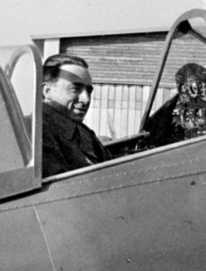
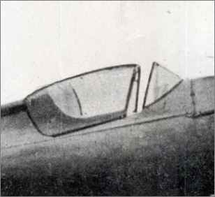
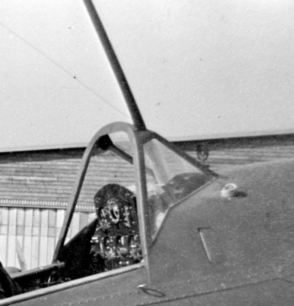
an interesting aspect, which we will detail below, is the fact that the windshield maintains the shape with curved sides, similar to that of the prototype, but with a flat front;
the rudder is provided with an in-flight adjustable trim tab, similar to that mounted on the elevator;
the logo on the propeller blade indicates that it is a VDM.
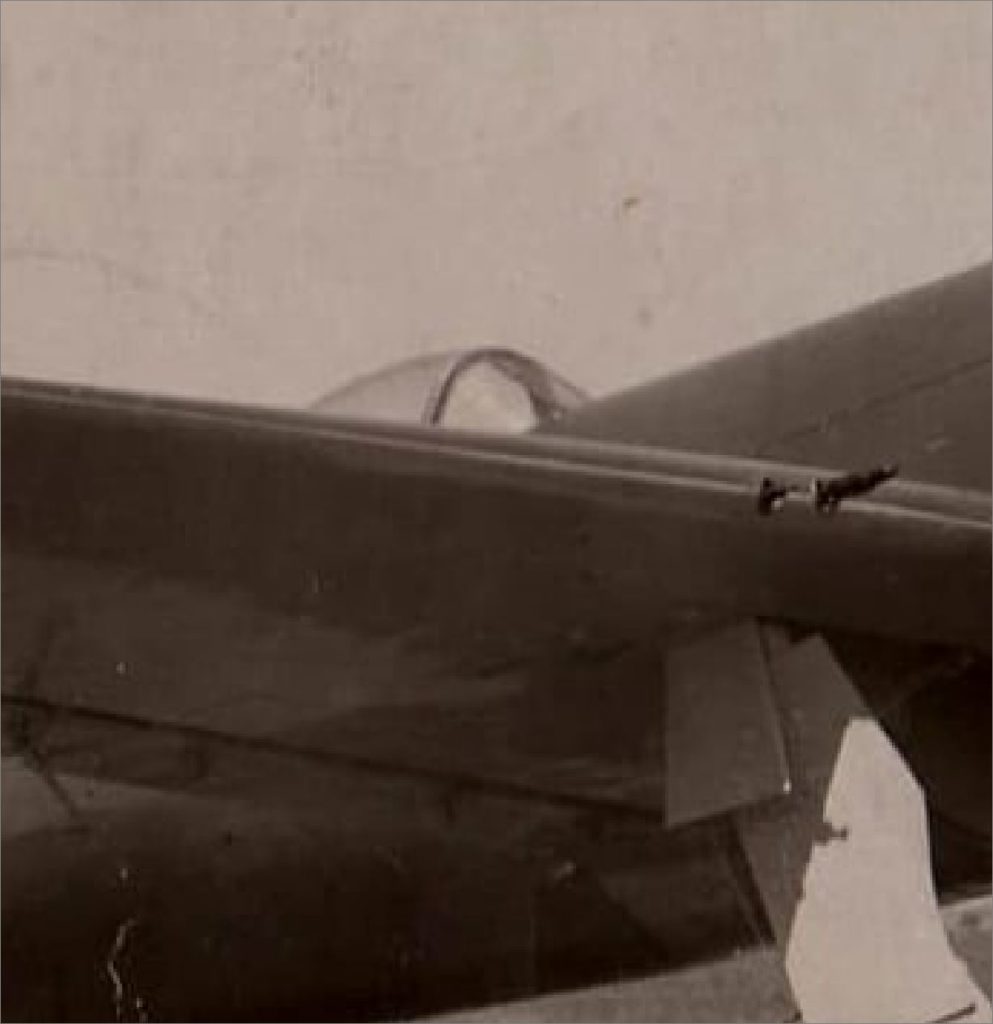
First variant of the closed canopy – we can observe the atypical shape of the windshield
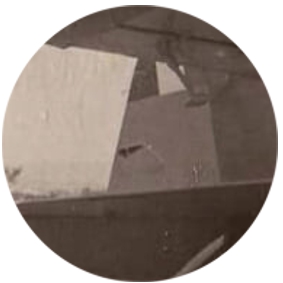
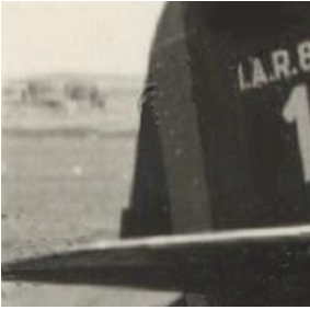
By zooming on the tail area, we can observe the control system of the trim tab mounted on the rudder surface
We would like to mention that it is the only photo available so far, which confirms the existence of the in-flight adjustable rudder trim tab, this being observed in several original blueprints.
This confirms and explains drawing “C-1112 – Details of the rear end of the fuselage” in which we can observe two pulleys mounted on the IX frame of the rear fuselage as follows:
left pulleys – for adjustable depth compensator cables;
right pulleys – for adjustable steering compensator cables.
The second variant
In this variant, the cooling slots behind the exhaust were abandoned and the rudder was changed, so the in-flight adjustable trim tab was replaced with one adjustable on the ground, a solution that will be kept throughout the entire production. The windshield and the canopy remain the same, in the atypical version.
The tricolor cockade can be seen on the underside of the right wing.
mass production tim tab – adjustable on the ground
The final variant
Number 1 – the final variant
On this plane, which will become the standard for the first series, the air intake is changed and the windshield is replaced with one with flat side windows. By default, the canopy also changes. An antenna mast is mounted and the gunsight grid system in front of the windshield.
The windshield in the new shape has a wider front window and the side windows are flat.
The grid of the gunsight can be seen in front of the windshield.
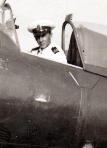
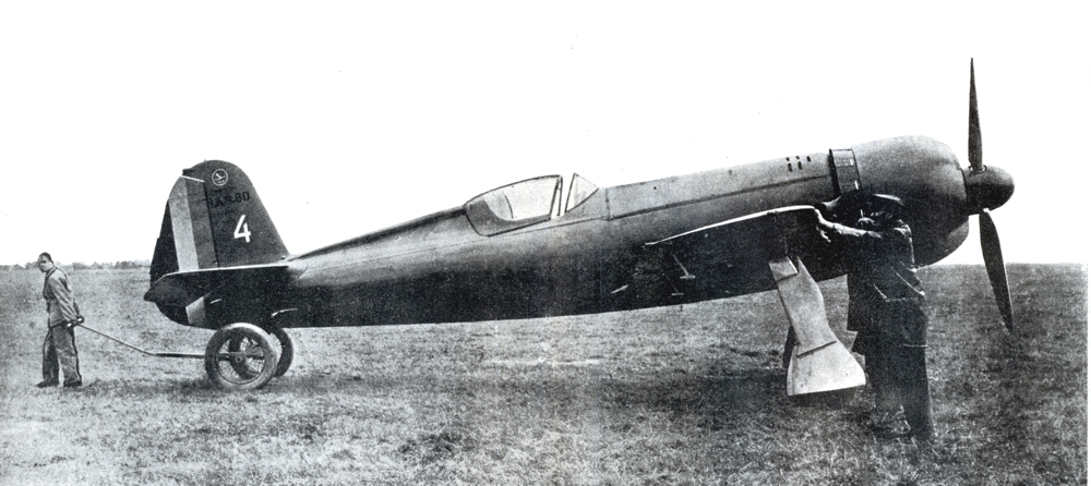
However, in early mass production, there were also airplanes that kept the old windshield, with semi-rounded sides.
No. 4 – windshield with curved sides
to be continued … ” the mass production”
Bibliography:
1. Dan Antoniu, George Cicos,IAR-80 "Le Héros Méconnu",Editura TMA Paris 2008