
In mass production the I.A.R. 80/81 aircraft were equipped with VDM (Vereinigte Deutsche Metallwerke) propellers, a German manufacturer with factories in Frankfurt-am-Main-Heddernheim and Hamburg, Gross-Borstel which equipped virtually the entire Luftwaffe during the war.
On the I.A.R. 80 prototype we can observe the typical VDM hollow spinner of an unusual long shape, sporadically found in the mass production series, as well as an early VDM oval logo.
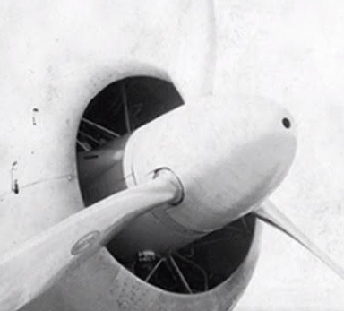
Propeller of the IAR 80 prototype with a VDM oval logo 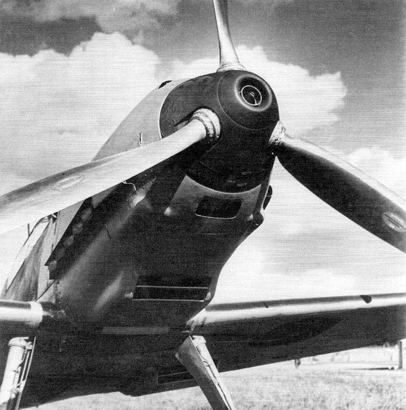
Propeller of the Bf-109 E with a VDM oval logo
I.A.R. 80/81 series were equipped with three-blade metal propeller with variable pitch type VDM 9-11 131. The propeller pitch was adjusted manually by the pilot through an electrically operated system, this system being used throughout production.
The following table lists the main characteristics of the propeller extracted from the airplane technical note: [2]
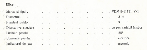
Propeller, Brand and type: VDM 9-11131 V-1; Diameter: 3 m; Nbr. of blades: 3; Special equipment: variable pitch; Pitch limits: 25 degrees; Pitch control: electrical; Pitch indicator: mechanical
The VDM type 9-11 131 was not a common type and is not found in the VDM parts list of the time [8], instead, as we will see below, the components are practically identical to those used in the initial variants of the Messerschmitt Bf 109 E. The main difference is that the IAR engine 14 K IV c 32 had a counterclockwise rotation (looking from the cockpit), opposite to the DB 601 A, N engine with which equipped the Bf 109 E.
To better understand the operation of the VDM system which equipped the I.A.R. 80/81 it is helpful to review the operating principle of the variable pitch propeller.
The propeller of an aircraft is essentially an airfoil which, like the wing of an aircraft, will provide the best aerodynamic efficiency at a certain angle of attack, the latter being generally determined by the blade angle relative to the central axis of the propeller and the air speed. In the case of a fixed pitch propeller, the optimum efficiency can only be obtained at a certain flight regime, for example during climb or constant speed cruise. To eliminate this shortcoming, the variable pitch propeller allows to adjust the blade angle and implicitly the propeller pitch (the distance traveled by the tip of the propeller along the central axis at a complete rotation). Thus, different values of the engine manifold pressure correspond to different speeds and positions of the propeller blades.
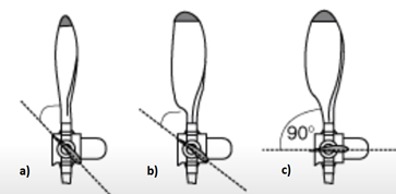
The diagram below shows 3 typical positions for:
- a) Low pitch, maximum engine RPM and low speed (take-off, climb)
- b) High pitch, nominal engine RPM and high speed (cruise flight)
- c) Feathered, for minimum drag in case of engine failure
Depending on the propeller pitch adjustment mode, VDM systems were of two types:
- Manual system in which the propeller pitch is selected by the pilot on the ground or in flight. This system could be converted to the automatic model.
- Automatic system, equivalent to contemporary ones, which was equipped with a constant speed unit (governor) that maintained a constant propeller speed by automatically adjusting the pitch at different airspeeds or engine power settings.
A unique feature of the VDM systems was the pitch indicator which we will address further on in this article. In both variants, the pitch indicators could be of the mechanical or electrical type.
The system used on the I.A.R. 80/81 was the manual one with mechanical indicator, this type of indicator being characteristic of single-engine airplanes. Unfortunately, the system was not improved by adapting to an automatic one, although this could be done relatively easily (as was the case with the Bf 109-E). As a matter of fact Maj. Hendrick of the Luftwaffe who tested the IAR 80 No. 2 on March 23rd 1941 highlighted the absence of the automatic system as a major shortcoming. It is not clear to the author which considerations constrained the I.A.R. manufacturer, perhaps the hope of equipping a more powerful engine, perhaps driven by cost or logistical considerations. Regardless, this limitation remained an important disadvantage for the I.A.R. 80/81, especially in air combat.
The propeller installation of the I.A.R. 80/81 is described in the diagram below [1]
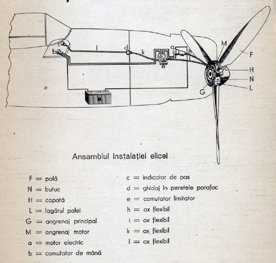
F = blade; N = hub; H = spinner; L = blade root; G = main gear; M = motor gear; a = electrical motor; b = control switch; c = pitch indicator; d = firewall guide; e = pitch limit controller; h, i, k, l = flexible shaft
The electrical motor (a) was connected to the blade angle adjustment main gear (G) by a flexible shaft (h). A similar flexible shaft (i) connects the main gear to the pitch limit controller (e). The latter had the role of keeping the blade angle within a predefined range of values, in the case of I.A.R. 80/81 this range being 25°. On the opposite side the limiter was connected to the mechanical indicator by two other flexible shafts (k, l) passing through the firewall. The manual switch (b) controls the increase or decrease of the propeller pitch by means of the limiter which in turn drives the electric motor.
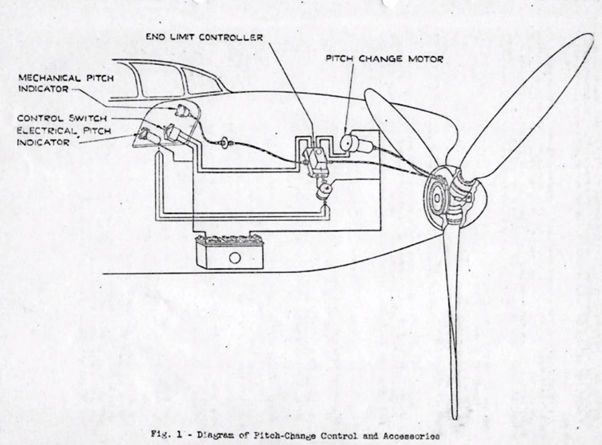
The following figure shows an English translation of the diagram from the VDM maintenance manual, Ed. 1939 [6]. Unlike the diagram in the I.A.R. manual, it also illustrates the variant with electrical pitch indicator with an additional capacitor on the circuit of the electrical indicator to limit interferences, the rest of the components being identical.
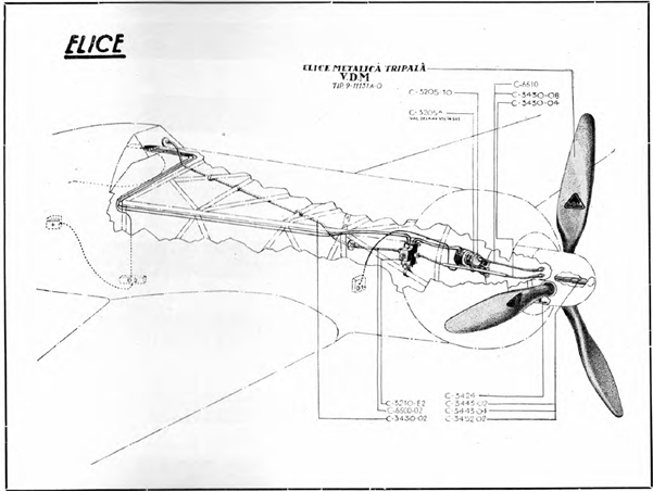
Most propeller components were supplied by the German manufacturer V.D.M. but some of the accessories (flexible shafts, mounting brackets, etc.) were produced at the I.A.R. factory, for example the flexible shaft of the electric motor C-3430-04 according to the I.A.R. nomenclature and other components illustrated in the diagram below:
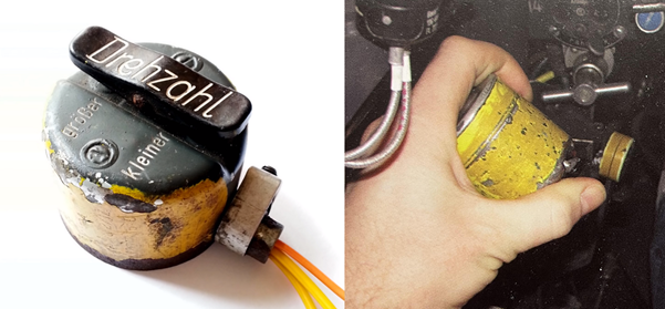
The pitch control switch (type VDM 9-9501) was a lever switch specially developed to operate the VDM adjustable propeller and was used to control the VDM 9-9500.12 electrical motor.
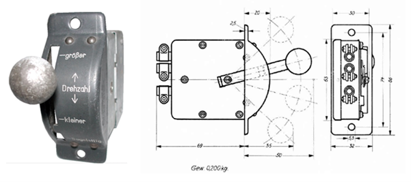
By continuously pressing the switch, the blade angle is adjusted, and implicitly, as shown above, the engine speed (‘Drehzahl’) at a certain position of the throttle lever. The switch had three operating positions and one stop position. In the ‘-großer’ position, the electric motor was operated in the direction of reducing the blade angle thus increasing the speed until the minimum blade angle was reached when the limiter automatically disengaged the motor. In the “-kleiner” position the engine was operated in the opposite direction resulting in a decrease in speed up to the position of the maximum angle. When the switch lever was released, it automatically returned to the neutral position at which the control motor was stopped. In the ‘Segelstellung’ position, the switch lever was held in place by a slot in the front panel. In this position, required for gliding in case of engine failure, the propeller pitch automatically returned to the large pitch corresponding to the maximum blade angle and the engine stopped automatically.
The switch was installed to the left of the pilot, above the throttle lever (position (z) in the figure below).
This type of switch was also used in the initial versions of the Bf 109 E and was later replaced with a more ergonomic system attached to the throttle, a forerunner of the modern HOTAS system (Hands On Throttle and Stick) used today on military aircraft. Unfortunately the I.A.R. did not benefit from similar improvements.
The propeller pitch indicator
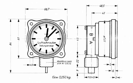
The position of the propeller blades could be read on the mechanical indicator VDM 9-9500.30 / 31, this type of indicator being characteristic of Luftwaffe aircraft.
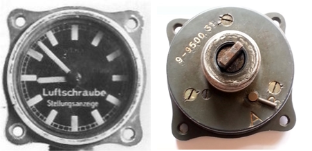
The indicator was in the shape of a clock without numerical markings and was read in the same way (for example, the engine was started at 10 o’clock, take-off at 12 o’clock, dive at 09:30, etc.). The minimum angle corresponded to 12 o’clock and 2200 engine RPM and the maximum to 09:30 o’clock and 1650 RPM.
This way pilots had an easy way to remember and set the relative positioning of the blades for different flight regimes, not being interested in the exact value of the blade angle. British engineers who analyzed the VDM system during the war could not understand the purpose of this indicator and considered it superfluous given that Allied aircraft were equipped with a lever to adjust the engine speed that worked the same as the throttle. By positioning this lever forward or backward, the pilot obtained the desired speed, the relative position of the lever having in this case also the role of approximate indicator of the propeller pitch.
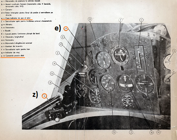
On the I.A.R. the VDM pitch indicator was located at the top left of the instrument panel (see position (s) in Figure 1 above representing the instrument panel).
A switch installed behind the indicator (marked A / B) allowed for changing the direction of rotation.
Author: Răzvan Mărgăuan
To be continued …
Bibliography:
1. Notița tehnică a avionului de vânătoare I.A.R. 80 cu motor I.A.R. 14 K. IV. C. 32, Brașov 1941
2. Notița tehnică a avionului I.A.R. 80 Ediția II-a, Brașov 1943
3. Catalog piese de schimb I.A.R. 80/81
4. Notița tehnică a motorului IAR-14K IV c32, Brașov 1942
5. John D. Waugh, Particulars of the German VDM, SAE Journal Vol. 52, No. 8, 1944
6. Bedienungs und WartungsVorschrift für die VDM-Verstelluftschraube, 1939
7. VDM-Verstelluftschrauben Geräte-Handbuch Beschreibung und Wirkungsweise sowie Bedienung und Wartung für elektr. Drehzahlregelanlagen, 1941
8. Ersatzteilliste für die VDM-Verstelluftschraube, 1939, 1941, 1944
9. Marco Fernandez-Sommerau, Messerschmitt Bf 109 Recognition Manual, Ian Allan Publishing, 2004
10. P. Blackah & M.V. Lowe, Messerschmitt Bf 109 Owners’ Workshop Manual, Haynes Publishing 2009
11. Principiile zborului, Aeroclubul României, București 2011
12. https://digital.deutsches-museum.de/item/73585/
13. ME109 Bf109 DB605 Engine Propeller pitch demonstration from a Luftwaffe Messersschmitt (https://www.youtube.com/watch?v=qIpZAu61OM8)
14. https://www.facebook.com/rww2aa/posts/iar-80-c-nr-264-esc49-gr-4-vtpilot-adj-av-olaru-aurel-shot-down-on-04021944-by-g/2454965397911586/